
- 미등록페이지
- Power Quality Energy Solutions
AHF/MCCMCC용 능동형 고조파 필터
-
AHF|MCC
제품 주요특징 MCC전용 능동형 고조파 필터[AHF/MCC]는 인버터 등 Motor 기동설비가 집중된 MCC반에 설치할 수 있도록 소형화하여, Motor의 기동, 정지 등, 부하변동이 많은 MCC반의 비선형 부하의 운전조건에 따라 최적의 TDD를 유지 할수 있도록 ATMA 제어기술을 탑재, MCC 계통의 전력품질 향상을 위한 최적의 Solution을 제공합니다. 카탈로그 다운로드
- MCC 최적화 설계
- MCC반 내부에 설치할 수 있도록 IGBT Power Module을 소형화하고 Filter 운용을 위한 Controller를 Module과 분리하여 MCC반 Door에 설치, 편리하게 사용할 수 있습니다.
- 최신의 고조파 관리 Algorithm 적용
- ATMA 제어기술을 탑재하여 경부하, 빈번한 부하변경 조건에서도 안정적인 고조파 관리가 가능합니다.
- ATMA(Automatic TDD Management Algorithm)
- 개선 목표 TDD를 설정하면 부하조건에 따라 필터 스스로 최적의 고조파 저감 조건을 산출하는 최슨의 고조파 필터 제어기술입니다.
- 7” Color Touch LCD 패널 적용
- 시인성이 뛰어난 컬러 화면에 모든 메뉴를 한글화 하여 누구나 손쉽게 사용할 수 있습니다.
- 전력 품질 Analyze
- 고조파 필터 설치 전/후의 전압, 전류의 왜형률 및 파형, 고조파 Spectrum, 최근 12개월의 월간 전력사용량, 월간 최대 사용전력 등 다양한 전력품질 전반의 정보와 트렌드를 확인할 수 있습니다.
- 진 / 지상 역률 개선
- 고조파 제거 기능 이외에 진상 및 지상의 역률을 목표 역률까지 개선할 수 있으며 불평형 부하의 개선이 가능합니다.
설치 효과Case Of Installation
○○ 정수장 전력품질 개선 사례입니다.
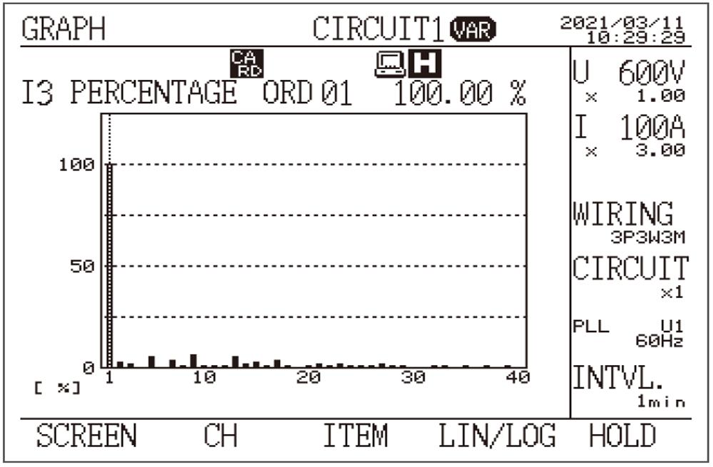
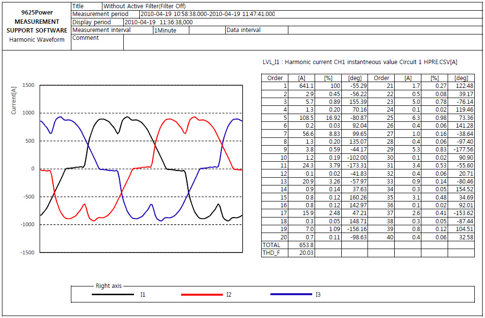
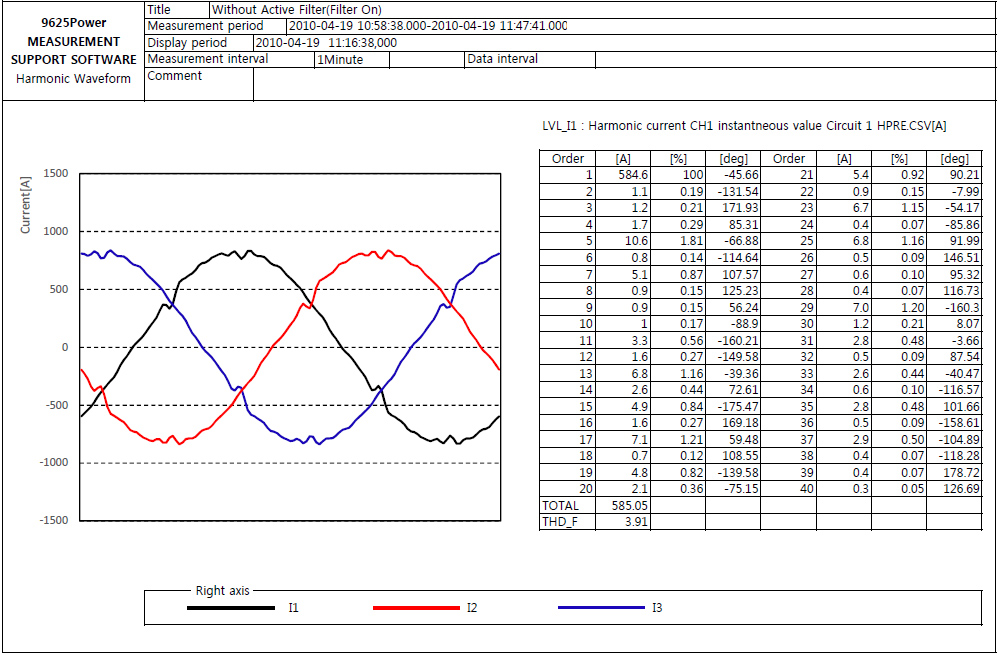
MCC에 AHF를 설치하고 설치 전/후 조고파 전류변화를 측정한 결과입니다. AHF 설치 후 3차, 5차, 7차 고조파가 95% 이상 감소됨을 확인할 수 있습니다.
-
고조파 필터 설치 전
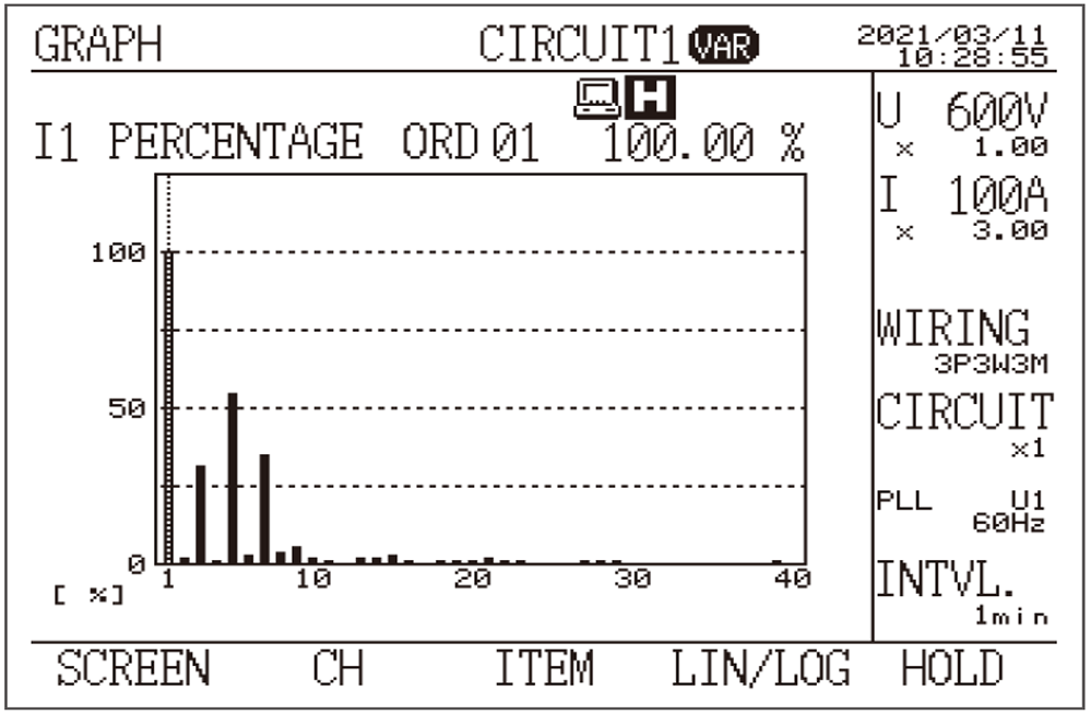
-
고조파 필터 설치 후
고조파 개선원리Harmonic Reduction Principle

- 1DC BUS CAPACITORAC-DC 정류 및 충전
- 2IGBTDC CAPCITOR의 On-Off 스위칭 간격을 조정하여(PWM) 고조파 보상을 위해 계통의 고조파와 크기는 갖고 180도의 위상차를 갖는 보상 파형을 출력합니다. DC CAPACITOR 충전 전하를 출력하므로 출력 파형은 구형파를 나타내게 됩니다.
- 3INVERTER INDUCTORIGBT로부터 출력된 구형파를 INDUCTOR의 과도현상을 이용해 정현파에 가까운 형태로 변환하는 임무를 수행합니다.
- 4LC FILTER CIRCUITINVERTER INDUCTOR을 거치면서 잔류하는 스위칭 노이즈를 제거합니다.
- 5HIGH FREQUENCY INDUCTORLC FILTER와 마찬가지로 불필요한 고주파수의 노이즈를 제거합니다. LC FILTER와 함께 LCL FILTER라고도 합니다.
MCC용 AHF 기기제원AHF Specification
SVG능동형 무효전력 보상설비
-
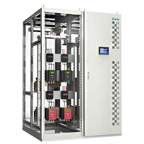
SVG
제품 주요특징 능동형 무효전력 보상설비 [SVG]는 부하 설비에서 발생하는 진/지상분 무효전력에 대해 실시간으로 분석하고 3Level IGBT PWM 기술을 활용하여 역률 보상 개선에 필요한 최적의 역률 관리 Solution을 제공합니다. 카탈로그 다운로드
- 진상+지상 무효전력 개선
- 지상분 무효전력 뿐만 아니라 진상분 무효전력까지 개선 가능. 심야시간/경부하 시간대 진상 전력으로 인한 전력비용 손실 최소화.
- 선형 역률 제어
- 3Level IGBT PWM 기술의 활용으로 출력전류를 더욱 정현파에 가깝도록 유지하여 선형 역률 제어 실현.
- 전력 품질 Analyze
- 역률개선 전/후의 전압, 전류의 왜형률 및 파형, 고조파 Spectrum, 최근 12개월의 월간 전력사용량, 월간 최대 사용전력 등 다양한 전력품질 전반의 정보와 트렌드를 확인할 수 있습니다.
- 산업현장 최적화 설계
- 7” Color Touch LCD 패널을 채택, 한글 Menu를 기본 지원하여 시인성 향상 및 대한민국 산업현장에 최적화.
SVG 설치효과
-
일반 SVC

- 콘덴서의 진상무효전력 공급이 20kvar, 40kvar, 60kvar의 3가지 경우로 제한되어 역률 관리에 한계 발생
- 역률 0.71~0.95사이를 오르내림
- 계단식 역률 보상
-
능동형 무효전력 보상설비 [SVG]

- 3Level IGBT PWM 기술의 활용으로 부하의 무효 전력을 최소화
- 역률 1로 일정하게 유지
- 선형 역률 보상
진상무효전력?
부하의 정전용량(C)로 인해 전압보다 앞선 위상(부하 임피던스 : XC > XL)의 전류가 흐를 때 생성되는 무효전력으로, 지상 무효전력과 마찬가지로 에너지 소모와는 무관하지만 송/배전 설비 및 발전설비의 용량을 증가를 유도하게 됩니다.


[ 한국일보 2014.07.25 기사내용 발췌 ]
에너지 절감을 위한 LED조명 설비의 일반화되고 있지만,
이에 따른 저급 LED의 유통으로 진상무효전력으로 인한 전력 비용이 증가하고 있습니다.
역률 요금체계 개정/진상 역률 검측
| 항목 | 변경전 | 변경 후 |
|---|---|---|
| 실시간 역률 요금제 도입 | 1개월 평균역률을 기준으로 역률요금 부과 | 30분 단위 역률의 1개월간 평균값 기준으로 역률요금 부과 |
| 심야시간 할증(23시~다음날 09시) 진상 역률 요금제 도입 | 심야시간대 진상역률에대한 할증요금 부과 | |
| 역률 요금 할인/할증률 조정 | 역률 1%당 기본 요금 1% | 역률 1%당 기본요금 0.5% |
HSVC진지상 무효전력 시스템
-
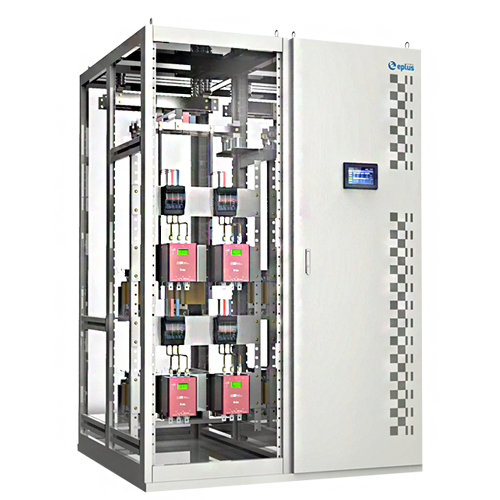
HSVC
제품 주요특징 진/지상 하이브리드 무효전력 보상설비 [HSVC]는 부하 설비의 지상분 무효전력뿐만 아니라 진상분 무효전력의 개선에 필요한 최적의 Condenser 조합 및 Shunt Reactor 조합을 선정, SCR Zero Crossing 제어기술을 활용해 돌입전류없이 투입/개방하여 궁극의 역률관리 Solution을 제공합니다. 카탈로그 다운로드
- 진상+지상 무효전력 개선
- 지상분 무효전력 뿐만 아니라 Shunt Reactor를 제어를 통해 진상분 무효전력까지 개선 가능. 심야시간/경부하 시간대 진상 전력으로 인한 전력비용 손실 최소화.
- 선형 역률 제어
- Shunt Reactor-Condenser간 상호 보상작용으로 Condenser 뱅크의 진상 무효전력 보상 단위(Step)를 최대 4배까지 세분화하여 선형 역률 제어 실현.
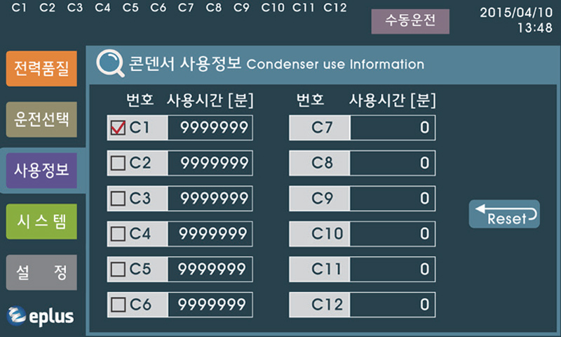
- 콘덴서 사용시간 균등제어
- 기존 FIFO(선입선출)방식의 Condenser 투입/개방 알고리즘에서 탈피, 동일 용량의 Condenser는 사용자가 지정(설정)한 시간을 기준으로 교번 운전하도록 하여 동일한 운전시간을 갖도록 제어.
- 산업현장 최적화 설계
- 7” Color Touch LCD 패널을 채택, 한글 Menu를 기본 지원하여 시인성 향상 및 대한민국 산업현장에 최적화.
HSVC 설치효과
-
일반 SVC

- 콘덴서의 진상무효전력 공급이 20kvar, 40kvar, 60kvar의 3가지 경우로 제한되어 역률 관리에 한계 발생
- 역률 0.71~0.95사이를 오르내림
- 계단식 역률 보상
-
하이브리드 SVC [HSVC]

- 콘덴서의 진상무효전력 공급이 5~60kvar까지 5kvar 단위, 12개 보상 단계(step)로 세분화되어 부하의 무효 전력을 최소화
- 역률 0.95로 일정하게 유지
- 선형에 가까운 역률 보상
진상무효전력?
부하의 정전용량(C)로 인해 전압보다 앞선 위상(부하 임피던스 : XC > XL)의 전류가 흐를 때 생성되는 무효전력으로, 지상 무효전력과 마찬가지로 에너지 소모와는 무관하지만 송/배전 설비 및 발전설비의 용량을 증가를 유도하게 됩니다.
[ 한국일보 2014.07.25 기사내용 발췌 ]
에너지 절감을 위한 LED조명 설비의 일반화되고 있지만,
이에 따른 저급 LED의 유통으로 진상무효전력으로 인한 전력 비용이 증가하고 있습니다.
역률 요금체계 개정/진상 역률 검측
| 항목 | 변경전 | 변경 후 |
|---|---|---|
| 실시간 역률 요금제 도입 | 1개월 평균역률을 기준으로 역률요금 부과 | 30분 단위 역률의 1개월간 평균값 기준으로 역률요금 부과 |
| 심야시간 할증(23시~다음날 09시) 진상 역률 요금제 도입 | 심야시간대 진상역률에대한 할증요금 부과 | |
| 역률 요금 할인/할증률 조정 | 역률 1%당 기본 요금 1% | 역률 1%당 기본요금 0.5% |
HSVC 기술
-

- 진/지상 역률제어 Controller 부하가 진상일 경우, 역률의 개선이 불가능했던 기존 APFR / SVC 시스템과 달리 Shunt Reactor 를 통해 지상분 무효전력을 공급하여 진상무효전력을 최소화합니다.
-

- SCR스위치-콘덴서용 역률보상용 콘덴서를 돌입전류(Inrush Current) 없이 투입/개방하는 스위치 기능 및 콘덴서 운전 중 고장(이상)여부를 진단(Trip)하는 기능을 수행합니다.
-

- SCR스위치-인덕터용 진/지상 역률제어 Controller의 제어에 따라 Inductor (Shunt Reactor)를 투입/개방하는 스위치 기능을 수행합니다.
-

- Inductor(Shunt Reactor) 부진상분 무효전력을 개선하기 위한 지상분 무효전력을 공급합니다.
-

- Condenser Bank 지상분 무효전력을 개선한기 위한 진상분 무효전력을 공급합니다. Condenser 이외에 고조파 공진을 억제 및 돌입전류를 제한하기위해 7~14%의 직렬리액터가 함께 사용됩니다.
SVC전자식 무효전력 시스템
-
SVC
제품 주요특징 전자식 무효전력 역률보상설비[SVC]는부하 설비의 무효전력 및 역률의 변화를실시간 분석하여, 역률 개선에 필요한최적의 Condenser 조합을 선정,SCR Zero Crossing 제어기술을활용해 돌입전류 없이 Condenser를자동으로 투입/개방하여 역률 관리에관한 최선의 Solution을 제공합니다.
또한, 역률 개선을 위해 설치하는Condenser를 SVC로 집중화하여수, 변전 설비 관리에 필요한 비용과시간을 최소화할 수 있습니다. 카탈로그 다운로드
- 역률 손실 최소화
- 일부 Condenser Bank 또는 SCR 스위칭 모듈에 이상이 발생하더라도 System 전체의 Trip 없이 건전한 Condenser는 운전을 지속할 수 있도록 하여 역률 손실을 최소화
- 콘덴서 사용시간 균등 제어
- FIFO(선입선출) 방식의 Condenser 투입/개방 알고리즘에서 탈피, 동일 용량의 Condenser Bank는 같은 운전시간을 갖도록 제어
실질적인 Condenser 사용시간 극대화 Solution
- 실시간 역률 개선
- 1주기(16.67msec) 이내 역률 개선
- 1Bank:1Module 개별진단방식의 독립 구조
- SCR 스위칭 모듈을 Condenser Bank별로 독립 설치/진단하여 개별 용량 확인 가능
사고의 2차 파급 방지 및 유지보수비용 최소화
- 콘덴서 실 사용시간 기록
- 역률 개선을 위해 Condenser Bank가 실제로 투입된 시간을 기록/Display
관리비용 최소화
- 7”Color Touch
LCD 패널 적용 - 화면을 한글화하여 누구나 손쉽게 사용할 수 있습니다. (TC-1200 Smart)
Smart SVC Color Display
-
-
7” Color 한글 지원 Touch LCD
· 한글 지원으로 손쉬운 사용
· Color Display로 시인성 증대
-
-
콘덴서 사용시간 균등 제어 및 실 사용시간 Display
· 단순 선입선출제어(FIFO)를 탈피, 동일한 용량의 콘덴서는 동일한 사용시간을 갖도록 Control
· 콘덴서의 실사용 시간을 누적 기록, 콘덴서 교체 주기 자료 제공
-
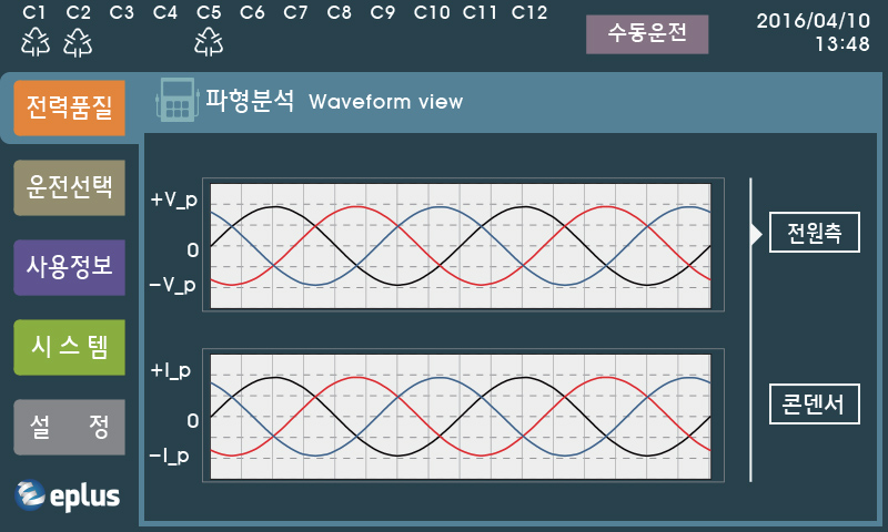
- 전원 측/콘덴서 측 전압·전류 파형 (Waveform) · 전력 품질 관리활동 지원
-
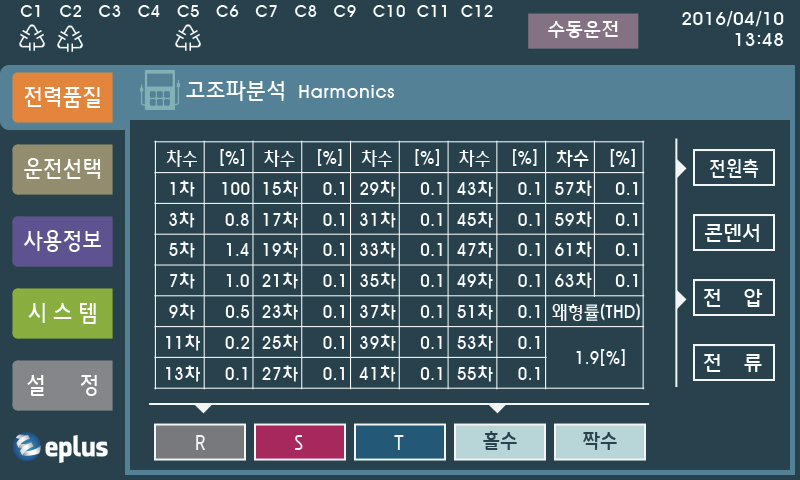
- 전원 측/콘덴서 측 전압, 전류 고조파 해석(1~63차) · 병렬 공진(전원 측 고조파 확대 현상) 억제를 위해 전원 측 및 콘덴서 측 고조파 해석
-
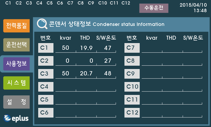
- 콘덴서 상태정보 확인 · Condenser bank 별로 kvar(용량), THD(고조파), S/W온도 Display · Condenser 교환정보 및 안정성 체크 가능
-
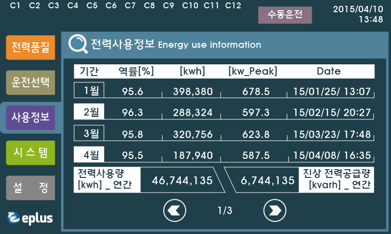
- Energy 사용관리 · 최근 12개월간의 매월 최대 부하 전력 및 최대부하 사용시간, 매월 전력사용량/역률을 저장하여 Energy 관리계획 수립의 기초자료를 제공
SVC 기기제원SVC Specification
CSD콘덴서 무접점 스위치
-
CSD
제품 주요특징 전자식 무효전력 역률보상설비[SVC]에제한적으로 사용되던 SCR 스위치제어기술을 순수 국내기술로 상용화해APFR 시스템 및 수동 On/Off 방식의 역률 개선시스템에서도 Condenser진단/보호 기능 제공 및 돌입 전류 없이역률 개선에 필요한 Condenser를 투입 / 개방할 수 있도록 함으로써 Condenser 운용의 안정성 확보 및 관리 및 유지보수에 필요한 비용과 시간을 최소화할 수 있습니다. 카탈로그 다운로드
- 무접점 스위치
- 무접점 방식의 전력반도체 소자인 SCR를 채택, 기계적 스위치 사용으로 인한 접촉 아크 방지
- Transient Free
- SCR의 Zero Crossing 제어기술을 활용 콘덴서 투입/개방 시 돌입전류 억제
- 콘덴서 운용 안정성 향상
- 콘덴서 진단을 위한 전압, 전류 검출 회로(PT/CT)를 내장, 콘덴서 과부하, 용량 감소 등의진단/보호(Trip)
- 전력품질 안정화
- 공진으로 인한 콘덴서 과대 고조파 유입을 검출, 고조파 확대 방지 및 전원공급시스템의전력품질 안정화
동작 특성Zero Crossing Technology
실시간 역률개선

- 콘덴서 투입(On) 신호 입력 후, 1주기 (1/60 sec)이내에 콘덴서가 투입되어 역률 개선이 이루어지므로 대용량 동력 설비 기동으로 인한 전압 Drop 현상을 최소화하게 됩니다.
Condenser Soft Switching 제어기술

- 1주기 이내(16.67msec 이내)에 콘덴서 투입/개방을 완료하여 역률 감소로 인한 전압강하 현상을 예방함과 동시에 콘덴서 돌입전류(Inrush Current) 발생을 억제합니다.
돌입전류 비교
| 접점방식 Switch(기존) | 무접점 스위치 C.S.D |
|---|---|
 |
 |
| 콘덴서 투입(On) 시 정격 전류의 최대 수십 배 돌입 전류 발생 | 콘덴서 돌입 전류의 억제 |
| Sag 발생 등으로 전원 품질 저하 | 전원 품질 향상 |
| 기계적 접점 Arc로 인한 접촉부 융착 및 화재 발생 | 접촉부 융착 및 화재 우려 없이 역률 개선 |
| 콘덴서 사용 수명 감소 | 콘덴서 및 스위칭 기기 사용 수명 연장 |
콘덴서사용상태 감시 DISPLAY
고속 연산이 가능한 CPU 및 전압/전류 검출 회로를 내장하여
콘덴서 사용 상태를 언제나 확인할 수 있습니다.

- 콘덴서 인가전압
전압 왜형률 THDv
스위치 온도

- 전압 Waveform
전류 Waveform

- 콘덴서 인가전류
전류왜형률 THDi
진상전력

- 전류 고조파 Spectrum
(1~15차)
CSD 기기제원CSD Specification
AHF능동형 고조파 필터
-
AHF
제품 주요특징 능동형 고조파 필터[AHF]는 부하 전류에포함된 고조파 성분의 전류와 역위상의 전류를 출력하여 중첩시켜줌으로써 고조파를 원척적으로 제거하는 필터로, 고조파차수 및 크기, 필터 설치 위치와 관계없이 효과적으로 고조파를 제거할 수 있으며 진/지상의 역률 및 불평형 부하전류까지 개선할 수 있어 산업현장의다양한 전력품질 향상 요구에 최적의 Solution을 제공합니다. 카탈로그 다운로드
- 최신의 고조파 관리 Algorithm 적용
- ATMA(Automatic TDD Management Algorithm) 제어기술을 탑재하여 경부하, 빈번한 부하변경 조건에서도 안정적인 고조파 관리가 가능하며 개선 목표 TDD를 설정하면 부하조건에 따라 필터 스스로 최적의 고조파 저감 조건을 산출하는 최신의 고조파필터 제어기술입니다.
- 7” Color Touch LCD 패널 적용
- 시인성이 뛰어난 컬러 화면에 모든 메뉴를 한글화 하여 누구나 손쉽게 사용할 수 있습니다.
- 진 / 지상 역률 개선
- 고조파 제거 기능 이외에 진상 및 지상의 역률을 목표 역률까지 개선할 수 있으며 불평형 부하의 개선이 가능합니다.
- 전력 품질 Analyze
- 고조파 필터 설치 전/후의 전압, 전류의 왜형률 및 파형, 고조파 Spectrum, 최근 12개월의 월간 전력사용량, 월간 최대 사용전력 등 다양한 전력품질 전반의 정보와 트렌드를 확인할 수 있습니다.
- 안정적인 고조파 제거 System
- 수동형 필터와 달리, 과부하 및 계통 공진 없이 필터의 설치 및 운용이 가능해 매우 안정적이며 복잡한 계통임피던스 분석 없이 간단히 설치할 수 있습니다.
- 제한 없는 고조파 제거 능력
- 3Level IGBT PWM 기술의 활용으로 출력전류를 더욱 정현파에 가깝도록 유지하여 불필요한 고조파 증폭없이 2~61차수의 고조파를 실시간으로 제거할 수 있습니다.
설치 사례Case Of Installation
○○ 금융센터 전력품질 개선 사례입니다.
개요 : 지하 7층, 지상 27층 규모의 건물에 6개소의 EPS분전반으로부터 전원을 공급받아, PC등 사무용 부하사용 중 분전반 N상인입선의 발열 및 과전류가 발견되어 6개소 모두 능동형 고조파 필터를 설치하여 전력품질을 개선한 사례입니다.
-
고조파 필터 설치 전
-
전류 왜형률(THD_I) : 87.42[%]
전압 왜형률(THD_V) : 6.50[%]
R상 전류 : 61.4[A]
N상 전류 : 94.1[A]
-
고조파 필터 설치 후
-
전류 왜형률(THD_I) : 7.4[%]
전압 왜형률(THD_V) : 3.1[%]
R상 전류 : 46.2[A]
N상 전류 : 9.5[A]
고조파 저감원리Harmonic Reduction Principle
- 1DC BUS CAPACITORAC-DC 정류 및 충전
- 2IGBTDC CAPCITOR의 On-Off 스위칭 간격을 조정하여(PWM) 고조파 보상을 위해 계통의 고조파와 크기는 갖고 180도의 위상차를 갖는 보상 파형을 출력합니다. DC CAPACITOR 충전 전하를 출력하므로 출력 파형은 구형파를 나타내게 됩니다.
- 3INVERTER INDUCTORIGBT로부터 출력된 구형파를 INDUCTOR의 과도현상을 이용해 정현파에 가까운 형태로 변환하는 임무를 수행합니다.
- 4LC FILTER CIRCUITINVERTER INDUCTOR을 거치면서 잔류하는 스위칭 노이즈를 제거합니다.
- 5HIGH FREQUENCY INDUCTORLC FILTER와 마찬가지로 불필요한 고주파수의 노이즈를 제거합니다. LC FILTER와 함께 LCL FILTER라고도 합니다.
AHF 기기제원AHF Specification
DPZ영상분 고조파 필터
-
DPZ
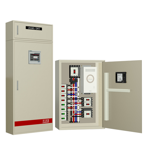
제품 주요특징 영상분 고조파 제거의 최적 장소인 분전반에 설치되어 중성선 및 전력 간선의 영상분 고조파로 인한 발열을 최소화하고 분전반의 Energy 사용량, 전력품질 등의 정보를 현장과 원격에서 손쉽게 확인할 수 있습니다. 카탈로그 다운로드
- 전력 품질 Analyze
- 개별 분전반의 전압, 전류는 역률, 전력사용량 정보는 물론, 고조파 전압, 전류를 계측, 전력 품질 전반의 정보를 확인할 수 있습니다.
- Energy 사용 정보 Monitoring
- 최근 12개월 최대사용전력(kw_Peak) 및 최근 12개월 전력 사용량(kWh) 정보 제공하여 분전반 단위의 Energy 사용 이력 확인이 가능합니다.
- 5” Color Touch
LCD 패널 적용 - 시인성이 뛰어난 컬러 화면에 모든 메뉴를 한글화 하여 누구나 손쉽게 사용할 수 있습니다.
- 소비전력 최소화
- 부하 설비로부터 고조파 발생이 검출되지 않을 경우, 운전을 정지함으로써 소비전력을 최소화한 고조파 필터입니다.
- 설치 효과 실시간 확인
- 고조파 필터를 통해 저감 되는 1~15차 고조파전류를 실시간 확인할 수 있습니다.
- 완벽한 자기보호
- 역상, 결상, 권선 온도 과열, 과부하 전류뿐 아니라 표피 효과로 인해 발열하기 쉬운 고조파 전류로부터 고속 보호하여 완벽한 자기 보호를 실현하였습니다.
영상분 고조파 성능 비교
| 제조사 | A사 | 지능형 영상분 고조파 필터 | 스마트형 영상분 고조파 필터 | |
|---|---|---|---|---|
| 제품등급 | 고급형 | DPZ-i3 | Smart DPZ | |
| Display |  7-segment 7-segment |
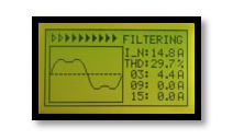 128 x 64 Graphic LCD 128 x 64 Graphic LCD |
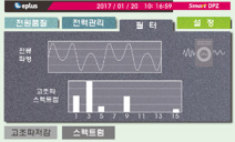 5” Color Touch LCD 5” Color Touch LCD |
|
| 성능 확인 | 중성선 전류(흡수 전류) 고조파 해석 불가 | 중성선 전류(흡수 전류)의 1~15차 고조파 해석 | 중성선 전류(흡수 전류)의 1~15차 고조파 해석 | |
| 온도 감시 | 가능 | 가능 | 가능 | |
| 역상/결상 보호 | 가능 | 가능 | 가능 | |
| 자기보호 | 과열, 중성선 전류(RMS) | 과열 / 중성선 전류(RMS) / 고조파 전류(Harmonic total RMS) / K-factor 검출을 통한 자동제어 | 과열 / 중성선 전류(RMS) / 고조파 전류(Harmonic total RMS) / K-factor 검출을 통한 자동제어 전력 | |
| 전력 품질 Monitoring | 전압 | 가능 | 가능 | 가능 |
| 전류 | 필터 중성선 전류 | 필터 중성선 전류 | 3상 부하전류/필터 중성선 전류 | |
| 전압 왜형률 | 불가 | 가능(THDv) | 가능(THDv) | |
| 전류 왜형률 | 불가 | 필터 중성선 전류 왜형률(THDi) | 3상 부하전류/필터 중성선 전류(THDi) | |
| 고조파 해석(Text) | 불가 | 필터 중성선 1~15차 고조파 해석 | 3상 부하전류 / 필터 중성선 전류 1~15차 고조파 해석 | |
| Waveform | 불가 | 필터 중성선 전류 Waveform | 3상 전압 / 전류 Waveform, 필터 중성선 전류 Waveform | |
| Spectrum | 불가 | 필터 중성선 전류 | 3상 전압 / 전류 Spectrum, 필터 중성선 전류 Spectrum | |
| Energy Monitoring | 유효전력 | 불가 | 불가 | 3상 유효 전력 합계 |
| 무효전력 | 불가 | 불가 | 3상 무효 전력 합계 | |
| 역률 | 불가 | 불가 | 진 / 지상 역률 | |
| 전력 사용량 | 불가 | 불가 | 전력사용량(매월 갱신) | |
| 전류 왜형률 | 불가 | 불가 | 매월 최대 사용 전력(전력+사용 시각) : 12개월 분 | |
| 월간 전력 사용량 | 불가 | 불가 | 매월 전력사용량 : 12개월 분 | |
| 원격감시(통신) | 불가 | 불가 | RS-485 Modbus Protocol | |
DPZ 기기제원DPZ Specification
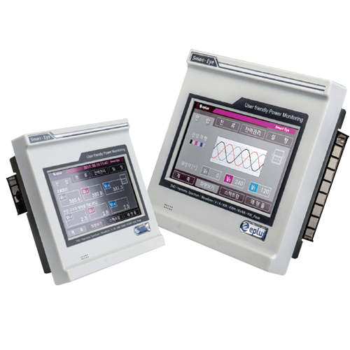
Smart Eye디지털 복합미터
-
Smart Eye
제품 주요특징 디지털 복합 미터 Smart-Eye는 수/ 배전 계통의 다양한 전력 정보에 대한 고정밀 계측 및 고조파, THD 등 전력 품질 분석이 가능한 고급형 디지털 복합 미터입니다.
한글 지원이 가능한 터치 방식의 5” Color LCD를 채용하여 시인성 및 사용이 매우 간단하며 RS-485 통신이 가능하여 감시반 구성에 용이합니다. 카탈로그 다운로드
- 계측 정밀도
- 전압은 50~460V에서 ±0.2% (Real Scale), 전류는 0.05~6A(CT 정격 5A 기준)에서 ±0.2% (Full Scale), 전력 및 전력량은 ±0.5 class를 만족합니다. 주파수가 변동되는 현장에서도 정밀도를 유지하여 신뢰성을 보장합니다.
- 다양한 전력 정보 계측
- 시인성이 뛰어난 Color 화면을 통해 40가지의 전력 정보를 표시할 수 있습니다.
- RS 485 Modbus Protocol
- RS 485 방식의 범용적인 Modbus RTU Protocol을 제공하여 원격 감시반 구현을 지원합니다.
- 광범위한 PT 전압 입력
- 별도의 PT없이도 최대 460VAC의 전압을 직접 입력할 수 있어 경제적이며 배선도 간편합니다.
- Energy 사용 관리
- 최근 12개월간의 매월 최대 부하 전력 및 최대 부하 사용시간, 매월 전력사용량을 저장하여 Energy 관리계획 수립의 기초자료를 제공합니다.
- 시인성 및 사용편의 제공
- 5” Color Touch 패널을 채용하여 3상 전력을 색상 별(흑, 적, 청색)로 구분하여 다양한 전력정보를 단일 화면에 Display 하였으며 모든 설정 및 선택 메뉴를 한글화하여 누구나 손쉽게 사용할 수 있습니다.
Smart Eye 제품 구성Smart Eye Constitution
- 전면부 구성

- 후면부 구성

Smart Eye 기기제원Smart Eye Specification
-
일반사항
형식 복합 디지털 파워 미터 Display 5” Touch LCD 사용언어 한글 결선방식 3P3W(Delta), 3P4W(Y) 입력 정격 주파수 50Hz, 60Hz 전압 PT 460V(2차 PT 110V) 전류 CT 0.25~6A 제어전원 AC 220V ± 10% 소비전력 4W 이하 입력부담 PT : 0.5VA이하 CT : 0.5VA이하 절연저항 DC 500V 10㏁ 이상 상용주파내전압 AC 2kV /1분간 뇌임펄스전압 AC 5kV 이상 1.2 × 50㎲ 표준파형인가 과부하
내량전류회로 정격전류×2배 : 3시간 인가 시 이상 없음,
정격전류×20배 : 2초 인가 시 이상 없음,전압회로 정격전압 × 1.15배 : 3시간 인가 시 이상 없음. 과도응답 Power Input 4kV(PT, CT) 정전기 Air 8kV, Contact 6kV 사용온도 -10℃~45℃ 보관온도 -20℃~55℃ 사용습도 습도 80% 이하 적용규격 IEC 602555, IEC 61000-4
CE_LVD : EN 610110-1:2010, CE_EMC : EN 61000-6-4:2007/A1:2011
EN 61000-6-2:2005, EN 61000-3-2:2014, EN 61000-3-3:2013통신방식 Modbus RTU /RS-485 크기(W×H×D) 144 × 144 × 62(mm) -
Display
전압 각 상 전압 Vr, Vs, Vt 정밀도 ±0.2% 선간 전압 Vrs, Vst, Vtr 정밀도 ±0.2% 전류 선 전류 Ir, Is, It 정밀도 ±0.2% 위상 상 전압 Vr, Vs, Vt 선 전류 Ir, Is. It 주파수 Hz 정밀도 ±0.5% 전력 각 상 유효전력 Pr, Ps, Pt 유효전력 합계 P 정밀도 ±0.5% 각 상 무효전력 Qr, Qs, Qt 무효전력 합계 Q 전력량 유효전력량 (월간) Wh 정밀도 ±0.5% 역률 3상 합계역률 P.F 정밀도 ±0.5% 고조파 전압 왜형률 Vr, Vs, Vt 의 왜형률 전류 왜형률 Ir, Is, It 의 왜형률 전압 Spectrum Vr, Vs, Vt 의 1~15차 고조파 스펙트럼 전류 Spectrum Ir, Is, It 의 1~15차 고조파 스펙트럼 전압 Waveform Vr, Vs, Vt 의 Waveform 전류 Waveform Ir, Is, It 의 Waveform 최대 전력 유효전력 Max W 최근 12개월
최대 사용전력기타 전력량 최근 12개월
최대 사용전력전력시보 매시 전력사용량


